5.3 - Transistor
Terminals and Types
- A transistor is an electronic component with three terminals.
| Terminal | Function |
|---|---|
| Emitter, E | Supplies charge carriers to the collector. |
| Base, B | A thin middle layer that controls charge-carrier flow from emitter to collector. |
| Collector, C | Receives charge carriers from the emitter. |
| Type | Structure and arrow direction |
|---|---|
| npn | A p-type base between n-type collector and emitter regions. The symbol’s emitter arrow points outwards, showing current from B towards E. |
| pnp | An n-type base between p-type collector and emitter regions. The symbol’s emitter arrow points inwards, showing current from E towards B. |
Base Circuit and Collector Circuit
- A transistor circuit has a base circuit and a collector circuit. A small base current controls a much larger collector current .
- In a transistor circuit with bulb and resistor in the base circuit, and bulb in the collector circuit:
- Switch open: The base circuit is incomplete, , and bulb is off. The transistor is off, so and remains off even though the collector circuit is complete.
- Switch closed: The large base resistance limits , so is dim. The transistor turns on and a larger makes bright.
- Base resistor limits the base current to prevent overheating and damage to the transistor.
- Base–emitter voltage must reach the minimum needed to turn on the transistor: 0.7 V for silicon and 0.3 V for germanium.
- Replacing an npn transistor with a pnp transistor requires reversing battery polarity in both circuits; , and emitter current reverse direction.
- For these operating circuits, ; when , .
Transistor as a Current Amplifier
- A small change in base current produces a much larger change in collector current. This allows amplification, such as in a singer’s loudspeaker system.
- The amplification factor, , is:
- Use the same current unit for and ; has no unit.
- The example graph of against is a straight line through the origin with positive gradient. Its gradient equals .
- With at :
- A base-current change of 1 mA corresponds to a collector-current change of 156 mA for this graph.
Potential Divider and Automatic Switching
- A potential divider gives a smaller output potential difference from a fixed supply. Connect and in series across input voltage ; take across .
- The same current flows through the two resistors in the divider calculation:
- The divider controls the base voltage and hence the base current. Turning the base current on or off allows the transistor to act as an automatic switch in the collector circuit.
Light-controlled Switch
- A light-dependent resistor (LDR) has high resistance in dim light and low resistance in bright light.
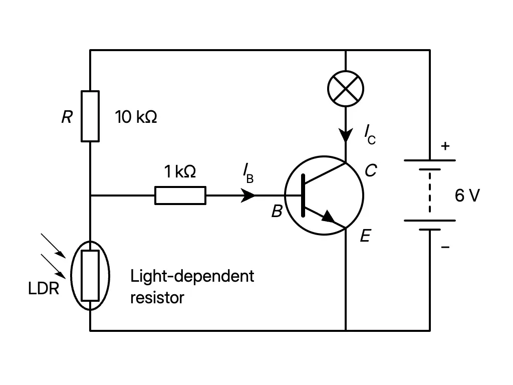
- In a 6 V light-controlled switch circuit, the 10 kΩ resistor is above the LDR in the potential divider. The base connects to their junction through a 1 kΩ resistor; the controlling voltage is across the LDR.
| Lighting | Circuit response |
|---|---|
| Dark | LDR resistance rises, so rises. When it exceeds the minimum base–emitter voltage, flows and turns on the transistor. A large flows and the bulb lights. |
| Bright | LDR resistance falls, so falls. Below the minimum base–emitter voltage, no base current turns on the transistor; the collector current and bulb remain off. |
- Application: Automatic street lights.
- In a 6 V d.c. light-controlled transistor kit, covering the LDR reduces the light intensity and turns on the transistor and LED.
Temperature-controlled Alarm
- A thermistor changes resistance with surrounding temperature. The thermistor shown has high resistance at low temperature and lower resistance when heated.
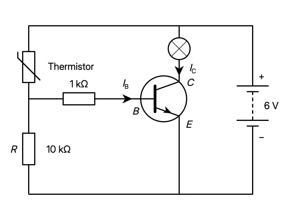
- In a 6 V temperature-controlled alarm circuit, the thermistor is above the 10 kΩ resistor in the potential divider. The base connects to their junction through 1 kΩ; the controlling voltage is across .
- The surrounding temperature rises and the thermistor resistance falls.
- Voltage across the thermistor falls, while voltage across rises.
- When exceeds the minimum base–emitter voltage, base current flows and turns on the transistor.
- A large collector current flows and the bulb lights.
- Application: Automatic switching in a temperature-controlled alarm system.
- In a 6 V d.c. heat-controlled transistor kit, warming the thermistor turns on the transistor and LED.
Answer practice questions to test your knowledge
Practice