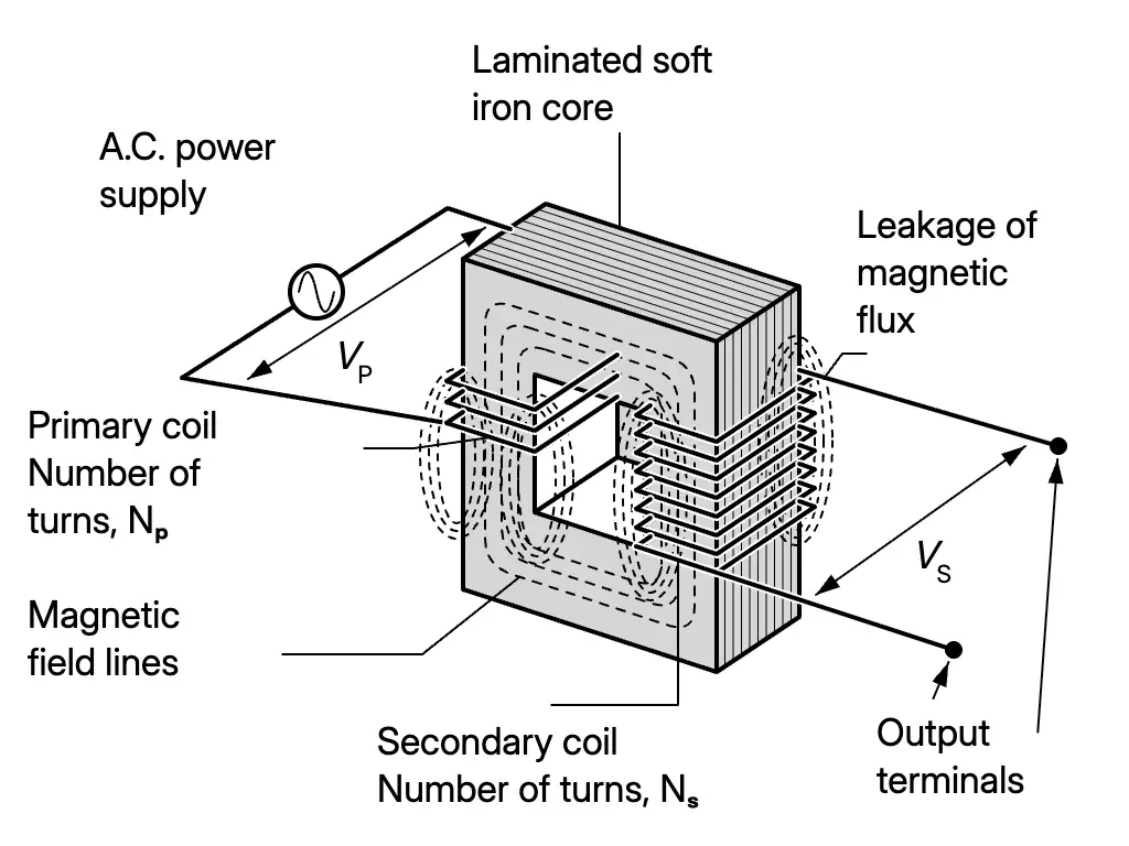
A simple transformer has a primary coil and secondary coil linked by a laminated soft iron core. It changes an input voltage to an output voltage of a different value.
VP and VS are the primary/input voltage and secondary/output voltage; NP and NS are the respective numbers of turns.
An alternating current supply produces alternating current in the primary coil.
The current creates a magnetic field that changes in magnitude and direction.
The soft iron core links magnetic flux from the primary coil to the secondary coil.
The changing magnetic field induces an alternating voltage across the secondary coil.
VPVS=NPNS
Type
Turns and voltage
Step-up transformer
NS>NP and VS>VP.
Step-down transformer
NS<NP and VS<VP.
Structure of a simple transformer
Ideal Transformer and Efficiency
Electrical energy transfers from the primary circuit to the secondary circuit, which supplies the connected equipment.
A real transformer loses energy, so its output power is smaller than input power.
Transformer efficiency, η, is:
η=Input powerOutput power×100%
Real transformers can have efficiencies as high as 99%.
An ideal transformer has no energy loss: η=100%, and input power equals output power. With primary current IP and secondary current IS:
VPIP=VSIS
Energy Losses and Improving Efficiency
Most energy losses occur as heat.
Cause and effect
Method of reducing loss
Coil resistance: current heats the long coil wires; heat escapes to the surroundings.
Use thicker copper wire to reduce resistance.
Eddy currents: the changing field induces currents in the iron core, heating it.
Use a laminated iron core made of thin sheets joined with insulating glue.
Hysteresis: repeated magnetisation and demagnetisation do not recover all the supplied energy; the difference heats the core.
Use soft iron, which needs less energy for magnetisation.
Magnetic flux leakage: some flux from the primary coil does not link to the secondary coil.
Wind the secondary coil over the primary coil so the primary flux passes through it.
Induction Cooker
A coil supplied with high-frequency alternating current creates a magnetic field changing at high frequency.
This field induces eddy currents in the base of the pan, heating the base. Eddy currents provide useful heating here, although they cause energy loss in a transformer.
Uses in Electrical Appliances
Step-down transformers
Step-up transformers
Mobile phone and notebook computer chargers, photocopy machines and welding machines.
Microwave ovens, defibrillators and X-ray machines.
Worked Example: Ideal Transformer
An ideal transformer receives 240V and supplies an electronic device with 27W at 18V. Its secondary coil has 60 turns.
Primary turns:
NP=VSVPNS=18240×60=800
Secondary current:
IS=VSPoutput=1827=1.5A
Primary current, using equal input and output power:
IP=VPVSIS=24018×1.5=0.1125A
Electrical Energy Transmission and Distribution
At the transmission stage, step-up transformers raise the cable voltage and reduce the cable current. This reduces electrical energy loss from the cable.
At the distribution stage, step-down transformers lower the voltage progressively to values suitable for industrial and residential consumers.
The illustrated system shows generation at 20 kV, transmission at 275 kV and subsequent levels of 132 kV, 33 kV and 11 kV. Heavy industry receives 33 kV, light industry 11 kV and residential homes 230 V.