4.1 - Force on a Current-carrying Conductor in a Magnetic Field
Force and Catapult Field
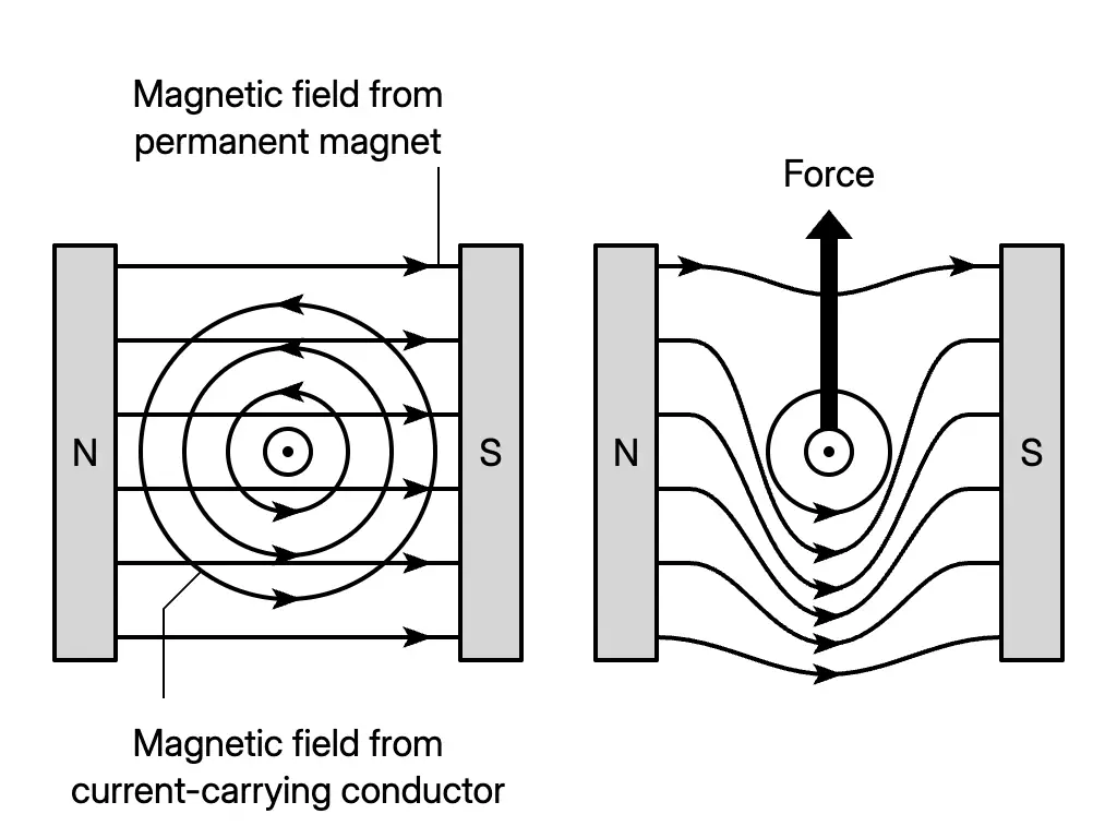
- A current-carrying conductor in a magnetic field experiences a force. Its direction depends on the directions of the current and the magnetic field.
- The field produced by current in the conductor interacts with the permanent magnet’s field. Their resultant field is the catapult field, which exerts a resultant force on the conductor.
- Where the two fields have the same direction, the resultant field is stronger; where they oppose each other, it is weaker.
- The force acts towards the weaker field region. A dot represents current out of the paper; a cross represents current into the paper.
- Use the right hand grip rule for the magnetic field around a straight conductor. The permanent magnet’s field runs from north to south.
- In a force demonstration, an uninsulated copper wire rests on two uninsulated copper rods between Magnadur magnets on a U-shaped steel yoke. A low-voltage direct current supply provides the current.
Fleming’s Left-hand Rule
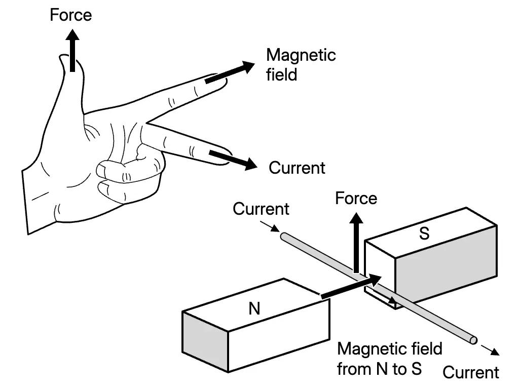
- Hold the thumb, index finger and middle finger perpendicular to one another.
- Point the index finger along the magnetic field, from north to south.
- Point the middle finger along the electric current.
- The thumb gives the force direction and hence the conductor’s motion.
Factors Affecting Force Magnitude
- Force increases with larger current or a stronger magnetic field. Bringing magnetic poles closer together strengthens the field.
- A copper frame swings higher when the force is larger. A conductor on uninsulated tracks travels further when the force is larger.
- An electronic balance can indicate force magnitude: an upward force on the copper wire produces an equal downward reaction on the magnets and balance pan. A larger force gives a larger balance reading.
- Reset the electronic balance to zero before switching on the current for each comparison.
- Comparisons use one magnet pair at 1 V and 2 V, then two magnet pairs at 1 V. These compare increased current and increased field strength; the balance readings are recorded in grams.
Turning Effect of a Coil
- A rectangular current-carrying coil rotates about its axis in a magnetic field.
- Catapult fields at opposite sides of the coil produce equal forces in opposite directions. This pair of forces turns the coil.
- This turning effect is the working principle of a direct current motor, which changes electrical energy into kinetic energy.
- Small motors occur in toys, portable drills and computer hard disks; larger motors occur in electric vehicles, lifts and factory rollers.
Working Principle of a Direct Current Motor
- The split ring commutator rotates with the rectangular coil. The carbon brushes remain fixed and maintain contact with the commutator.
- In the illustrated first half rotation, current flows : side AB experiences a downward force and side CD an upward force.
- After half a turn, each brush contacts the other commutator half. Current in the coil reverses to : AB experiences an upward force and CD a downward force.
- These changes keep the coil rotating in the same direction in successive half rotations.
Speed of Motor Rotation
- Rotation becomes faster when the current in the coil increases, the magnetic field becomes stronger, or the coil has more turns.
- A simple motor comparison uses a copper coil supported by large paper clips, Magnadur magnets and a direct current supply. Increasing the supply from 4.0 V to 6.0 V, adding a magnet and increasing the coil turns demonstrate these effects.
- Precautions: switch off immediately after observing; allow current to flow briefly so that the copper coil does not overheat.
Brushed and Brushless Motors
- Both contain a magnet and coil and use magnetic force to produce rotation.
| Brushless motor | Brushed motor |
|---|---|
| Coil is stationary; magnet rotates. | Magnet is stationary; coil rotates. |
| No carbon brushes or friction between brushes and commutator. | Brush–commutator friction wears out the carbon brushes. |
| No sparking at the commutator. | Sparking occurs at the commutator. |
| Quieter operation. | Louder operation. |
Homopolar Motor
- A simple homopolar motor uses a neodymium magnet, an AA dry cell and copper wire.
- Michael Faraday constructed and demonstrated a homopolar motor in London in 1821.
Answer practice questions to test your knowledge
Practice