Resistance relates potential difference and current: R=V/I, measured in ohms, Ω.
An ohmic conductor obeys Ohm’s Law: at constant temperature, V∝I and resistance remains constant. Its V against I graph is a straight line through the origin.
A non-ohmic conductor does not obey Ohm’s Law. A filament bulb produces a curved V against I graph through the origin; voltage and resistance increase as current increases.
Tungsten wire is ohmic at constant temperature. In a lit bulb, increasing current heats the filament and increases resistance, so the bulb displays non-ohmic behaviour.
Standard wire gauge (s.w.g.) indicates wire diameter: a larger gauge number means a smaller diameter.
Experiment 3.1: Current and Potential Difference
Aim: Compare the relationship between current and potential difference for constantan wire and a filament bulb.
Inference: Potential difference across a conductor depends on current.
Hypothesis: Greater current produces a greater potential difference.
Variables: Manipulated — current; responding — potential difference. Keep the constantan wire’s temperature, diameter and length constant; for the bulb, keep filament length constant.
Apparatus: 1.5 V dry cell, cell holder, switch, connecting wires, ammeter, voltmeter and rheostat; for constantan, a metre rule and 20 cm s.w.g. 24 wire; for the bulb, a 2.5 V, 3 W filament bulb.
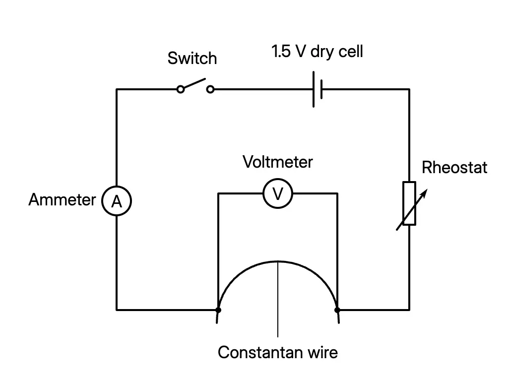
Connect the ammeter, rheostat and constantan wire in series with the cell and switch; connect the voltmeter across the wire.
Close the switch and adjust current to 0.2 A. Record the potential difference.
Repeat at 0.3, 0.4, 0.5 and 0.6 A.
Replace the wire with the bulb. Record potential difference at 0.14, 0.16, 0.18, 0.20 and 0.22 A.
Plot V against I for both conductors.
Results and conclusion: Constantan gives a straight line through the origin and constant resistance. The bulb gives a curve with an increasing rate of voltage increase and increasing resistance.
Precautions: Tighten connections, avoid parallax when reading meters, and open the switch immediately after each wire reading to keep its temperature constant.
Circuit for investigating a constantan wire
Series and Parallel Circuits
Circuit
Current, potential difference and effective resistance
Series
Current is the same through each resistor: I=I1=I2=I3. Potential differences add: V=V1+V2+V3. Resistances add: R=R1+R2+R3.
Parallel
Current splits at junctions: I=I1+I2+I3. Potential difference is the same across each branch: V=V1=V2=V3. 1/R=1/R1+1/R2+1/R3.
Worked Combination Circuits
A 2Ω resistor is in series with parallel 4Ω and 12Ω resistors across 6 V:
Rparallel1=41+121,Rparallel=3Ω,R=2+3=5Ω
I=56=1.2A,V2Ω=1.2(2)=2.4V
V4Ω=V12Ω=6−2.4=3.6V
I4Ω=43.6=0.9A,I12Ω=123.6=0.3A
A second 5 V circuit has two 4Ω resistors in series with a parallel section between A and B. That section contains two 2Ω resistors in series in one branch and a 4Ω resistor in the other:
Rbranch=2+2=4Ω,RAB1=41+41,RAB=2Ω
R=4+4+2=10Ω,I=105=0.5A,VAB=0.5(2)=1.0V
Experiment 3.2: Wire Length
Aim: Determine the relationship between wire length and resistance.
Inference: Resistance depends on length. Hypothesis: A longer wire has greater resistance.
Apparatus/material: Two 1.5 V dry cells, cell holder, switch, connecting wires, ammeter, voltmeter, crocodile clips, rheostat, metre rule and 110.0 cm of s.w.g. 24 constantan wire.
Connect the wire, ammeter and rheostat in series with the 3 V supply. Connect the voltmeter across the wire length between clips P and Q.
Set the measured length to 20.0 cm, close the switch and adjust current to 0.5 A.
Record V. Repeat for 40.0, 60.0, 80.0 and 100.0 cm.
Calculate R=V/I for each length and plot R against l.
Result and conclusion: A straight line through the origin shows R∝l.
Precaution: Keep wire temperature constant because temperature changes affect resistance.
Experiment 3.3: Cross-sectional Area
Aim: Determine the relationship between cross-sectional area and resistance.
Inference: Resistance depends on cross-sectional area. Hypothesis: A larger area gives smaller resistance.
Variables: Manipulated — resistivity, changed by changing material; responding — resistance; constant — length, diameter and temperature.
Apparatus/materials: Two 1.5 V dry cells, cell holder, switch, connecting wires, ammeter, voltmeter, crocodile clips, rheostat, metre rule, and 35.0 cm lengths of s.w.g. 24 constantan and nichrome wires.
Connect 30.0 cm of constantan between P and Q, with the ammeter in series and voltmeter across the wire.
Close the switch, adjust current to 0.5 A and record V.
Repeat with the same length of nichrome wire.
Record I and V, then calculate R=V/I for each material.
Conclusion: For equal length, area and temperature, greater resistivity gives greater resistance. Nichrome has greater resistivity than constantan.
Precaution: Keep temperature constant.
Material
Resistivity / Ωm
Copper
1.68×10⁻⁸
Constantan
49×10−8
Nichrome
100×10−8
Wire Resistance
Combining the relationships gives:
R∝Al,R=Aρl,ρ=lRA
Applications and Types of Material
Heating elements: An electric rice cooker’s heating plate uses a durable conductor with high resistivity and a high melting point.
Connecting wires: Fine copper wires have low resistivity, preventing rapid heating when current flows.
Material type
Electrical behaviour
Non-conductor
Good insulator with the highest resistivity; examples include plastic and wood.
Semiconductor
Conducts better than an insulator but less well than a conductor; resistivity lies between them. Examples include silicon and germanium.
Conductor
Conducts electricity and has low resistivity; examples include iron and carbon.
Superconductor
Conducts without resistance; resistivity becomes zero at its critical temperature, Tc, so current flows without energy loss. Superconductor coils are used in MRI.
Worked Wire-resistance Calculations
Use l in metres, A in square metres and ρ in Ωm. For a circular wire, A=πr2 and radius is half the diameter.